Kevin Harvick’s #29 car was hot. No, not overheating, but generating a lot of horsepower from its hand-ground manifold according to dynamometer tests performed after last year’s Auto Club 500 race in California.
Replicating the Original Magic
Intake manifolds help control the amount of air and fuel that reaches cylinders, directly affecting power generated by the engine. Basically, the more fuel and air that can be fed to the cylinders, the more power the engine creates. There are tradeoffs, of course, including the wear and tear of parts when dealing with larger volumes of fuel and air.
An intake manifold comprises eight runners that deliver the air and fuel to the cylinder heads, and the plenum, a chamber where the runners come together under the carburetor. The manifold comes to RCR and other GM racing teams as a standard, NASCAR-approved part number from GM Racing. The openings in the runners and plenum are intentionally small, giving race teams leeway to grind them to their own shape and size.
Hand-grinding of intake manifolds, cylinder heads, and other engine parts is a mix of art, engineering, and serendipity. It is done by professionals with years of experience and practice; they know intuitively what works and what doesn’t. The problem is making this process repeatable: Just as a sculptor cannot create an exact replica of a piece created from raw marble, neither can an engine technician repeat the grind on a runner in exactly the same way each time.
Two Failed Trials
RCR first tried to recapture the magic of a special manifold by taking measurements and grinding by hand. Although the team came somewhat close to the original, the process wasn’t fast or repeatable enough.
In its second attempt, RCR used a CMM machine to do the measuring and traditional CAD/CAM software to create a digital model from the scan data. That process also fell short of the team’s needs, according to Rick Grimes, RCR’s Manufacturing Manager.
“It was complicated to create the surfaces in standard CAD/CAM software,” he says. “The additional time required to create a usable surface in our software would cause us to miss our deadline, which wasn’t acceptable.”
When the first two approaches didn’t work, it was natural that RCR would turn to technology from Geomagic. A year before, the racing team used Geomagic software to create an exact digital replica of a GM SB2 engine block, which RCR and other GM teams plan to use for engineering analysis. RCR also uses the software to digital reconstruct hand-ground cylinder head ports.
Creating More of the Same
A week after the Auto Club 500 race, Harvick’s #29 car was once again running on a chassis dynamometer, this time at RCR’s facilities in Welcome, N.C., outside of Charlotte.
The dynamometer simulates a car’s performance on typical track conditions within a laboratory environment. A large roll or drum acts as the mechanism for applying a realistic road load. The rate at which the car is able to accelerate the drum provides information on the amount of energy transferred from the tires to the drum’s surface.
Engine speed and drum acceleration combine to produce data on wheel horsepower – the amount of power transmitted to the pavement by the wheels. This data is plotted against time, speed or distance to produce graphs that depict performance characteristics. The results are saved in databases to use in future comparisons.
Dynamometer tests for the #29 car confirmed that it was generating five extra units of horsepower and 200 more useable RPMs than any other RCR manifold. Not wasting a second of time, the RCR team took the intake manifold off of the engine and set it up for scanning.
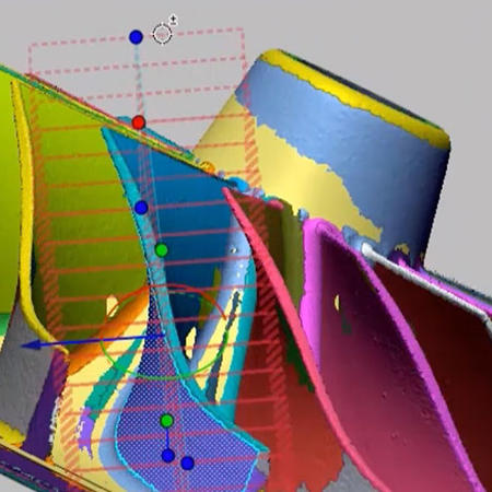
Geomagic Design X (Studio) software created an exact digital replica of a hand-ground intake manifold.
“It was a one-off, hand-ground manifold that was generating great power numbers,” says Grimes. “We needed to quickly produce identical manifolds for our two additional Nextel Cup teams.”
The still-warm intake manifold was bolted onto a Browne & Sharpe CMM system with an SP600M continuous scanning head. Although it would take more time to collect data than an optical scanner, the CMM system was selected because it allowed the manifold to stay in tact. Optical scanning would have required cutting down the center of the manifold, making plastic molds of the openings, and then scanning the molds.
RCR digitized half of the manifold, reaching as much as possible given the limitations on head angle and length of the CMM styli. The four runners on half of the engine were scanned individually, since each is different, with unique angles and volumes. The manifold was then turned over, and the plenum area scanned. The process took about five days; 10 to 12 hours each day.
“Every port is different. Working at different angles and fine tuning the scanning parameters is necessary to collect the specific data,” says Grimes.
From One-of-a-Kind to Repeatable
The ASCI files of point-cloud data collected by the CMM system were imported into Geomagic Design X software. The runners were saved in a 1.38-MB file and the plenum in a 1.06-MB file. The files were referenced to the same coordinate system, and the two data sets merged into one point cloud containing 84,000 points.
Outliers – the stray points outside of the model itself – were removed, and a uniform sample was created for consistent data representation. The point-cloud model was then converted automatically into a polygon model. Holes in the polygon were filled by the software and intersections were tested for validity.
Next, came auto surfacing, where Geomagic Design X turns the polygon model into a watertight NURBS surface. The automatically generated surface patches were very close to the final quality needed; the only work required was minor editing and interpolating surfaces in areas for which scanner data was not available. Grids were constructed on the revised patch layout, and the software created the final surface model for half of the manifold. The model was saved as an 11.3-MB IGES file and imported into Pro/ENGINEER software.
RCR copied and rotated the model in Pro/ENGINEER to generate the other half of the manifold. The complete model was then imported into a five-axis surfacing program, which generated the tool path for a CNC machine on the shop floor. The new manifold was cut by the CNC machine in seven hours. It typically takes 35 hours to hand grind a manifold, according to Grimes.
A Digital Duplicate
Tolerance for the new manifold was within plus or minus 10 thousandths of an inch of the original – a tolerance that was maintained for every subsequent manifold created from the digital model.
“The surface quality was impressive,” says Grimes. “We had no problems creating the toolpath, and even with the surface interpolation, the models were almost exact duplicates of the original, hand-ground manifold.”
As the first manifold came off the CNC machine, it was taken to the engine shop for polishing and testing on the dynamometer. The manifold generated the same peak power as the original, and the power curves were nearly identical. It was installed in the engine of the car driven by Jeff Burton, and sent on its way to the next race – the Pocono 500.
Since that race in June 2004, digitally reconstructed manifolds have been used on each of RCR’s Nextel Cup Series cars, consistently generating impressive horsepower and RPM statistics. Having proven itself within RCR’s time-sensitive, performance-driven environment, it appears that the reverse-engineering process will be a part of the racing team’s future.
“I see reverse engineering with Geomagic software continuing to improve our ability to capture and recreate special design features in our engines and cars,” says Grimes. “The speed, ease of use, and accuracy of this process make it a natural for meeting the demands of Nextel Cup racing.”
Richard Childress Racing captured a hand-ground intake manifold with a Browne & Sharpe CMM system.
Tolerance for the new manifold was within plus or minus 10 thousandths of an inch of the original – a tolerance that was maintained for every subsequent manifold created from the digital model.
“The surface quality was impressive,” says Grimes. “We had no problems creating the toolpath, and even with the surface interpolation, the models were almost exact duplicates of the original, hand-ground manifold.”
As the first manifold came off the CNC machine, it was taken to the engine shop for polishing and testing on the dynamometer. The manifold generated the same peak power as the original, and the power curves were nearly identical. It was installed in the engine of the car driven by Jeff Burton, and sent on its way to the next race – the Pocono 500.
Since that race in June 2004, digitally reconstructed manifolds have been used on each of RCR’s Nextel Cup Series cars, consistently generating impressive horsepower and RPM statistics. Having proven itself within RCR’s time-sensitive, performance-driven environment, it appears that the reverse-engineering process will be a part of the racing team’s future.
“I see reverse engineering with Geomagic software continuing to improve our ability to capture and recreate special design features in our engines and cars,” says Grimes. “The speed, ease of use, and accuracy of this process make it a natural for meeting the demands of Nextel Cup racing.”