By Yates Fletcher, Engineering, Geomagic
The previous and only other time I fell off my bike, I was riding no-hands on my brand-new red Schwinn (showing off for Donna McCulloch as I recall) when I ran afoul of a displaced manhole cover. More recently, I locked the front wheel while braking on a slick downhill turn, but the result was much the same in both cases: I instinctively broke the fall with my hand. But as the latest fall revealed, the intervening 50 odd years had stolen much of my childhood resilience. This time it hurt a little more. There was swelling and stiffness in the wrist joint, but as there were no obvious signs of a break, I decided to wrap it in an ACE bandage until I could get an appointment with the orthopedist. There was just one problem: The bandage didn't ease the pain in my wrist as I wrote code for and tested Geomagic Studio 2013.
I thought I could build a more comfortable wrist support. After all, I have limited expertise with wrist injuries from being the father of a gymnast. As we all know, the treatment of choice for a wrist compression injury is to immobilize the joint with a splint or cast. Casts, on one hand, provide superior support and a customized fit, but you can't remove them, and they're incredibly itchy. Splints, while they don't provide as much support, are generally sufficient for a sprain or even an occult fracture, and they are removable. Yet a splint is also uncomfortable because the support is seldom shaped to exactly fit the area to which it is applied. The wrapping on a splint is not force-neutral - it must be tight enough to bind the joint to the support, and even this small amount of force applied constantly can eventually cause aching and discomfort at pressure points. So if we could combine the customized fit and stability of a cast with the removability of a splint, we might be on to something.
Maybe there was a solution in the software I was building.
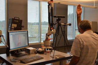
I was aware of an application years ago where Geomagic-created 3D models of scanned limbs were used to manufacture lightweight, removable, plastic casts, but the process required industrial-grade scanning and manufacturing equipment, which rendered it too expensive for general use. Since then two developments, both of which make this particular application much more accessible, have taken place. The first, a successful project I worked on here at Geomagic, uses several complementary voxel-space algorithms and the massive computing power of a modern graphics processor (GPU) to turn the data stream produced by a moving Microsoft Kinect® gaming sensor into a 3D model of the environment it sees. The second development was the evolution of 3D printers, namely they had become more affordable, and we now have several in house. So with several days to go before my appointment with the orthopedist, I used a Microsoft Kinect and our 3D printer to try a solo build of my own customized cast.
Scanning
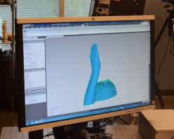
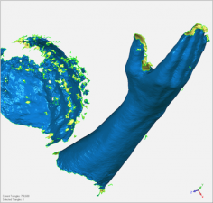
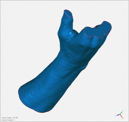
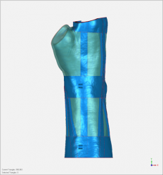
The scanning process (since it used Geomagic software :)) was the simplest and fastest part of the process. The interactive interface in Geomagic Fuse (our Geomagic Studio plug-in for Microsoft Kinect) allowed me to quickly define the scanning volume as a cube, with approximately two feet on each side, that started three feet in front of the Kinect: the distance where the device sees things most accurately. I raised my arm into the middle of the scan volume above my head and began slowly rotating on a stool during the 12-second scan. (Image below, left) All 100+ megabytes of range data from my arm that the Kinect produced during this time were being integrated into a high-resolution voxel representation and displayed on the screen in real time. After 15 more seconds of post-processing, Fuse presented me with a 750,000-polygon model of the arm, accurate to within 2 to 3 millimeters and ready for export as a .wrp, .obj or .stl file. (Image below, right) Compared to the workflow complexity and equipment cost of most commercial scanning processes this was almost literally a snap!
 Cleanup
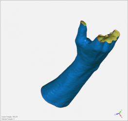
As with any scanning process, the model produced by Fuse had numerous minor cosmetic and topological imperfections (e.g., inaccurate or missing data from between my fingers). Fortunately there is a wizard-like command in Studio called Mesh Doctor that automatically handles the vast majority of these problems; after invoking it, I had only a few residual holes to fill. Interestingly, a certain percentage of the returns from the sensor were from the hairs on my arm instead of the skin, causing a slight unnatural roughness in the surface of the model, which was quickly corrected by the Reduce Noise command. Finally, I used the Trim With Plane command to trim the ends of the model, leaving an eight-inch section (Image left) centered on the wrist: the maximum length that can be reproduced by our 3-D printer and the part of my arm that would be covered by the cast.
Constructing the Shell
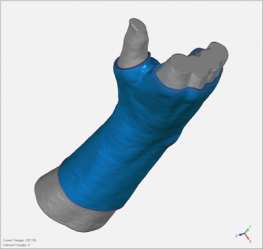
With a clean model of the part of the arm to be covered, the next task was to construct the enclosing shell, which would become the cast. To form the inner surface, I scaled up the model, and I formed the outer surface by trimming the inner surface slightly at each end and using the Offset command to expand it by the desired thickness. (Images below) After closing off the ends of both the inner and outer surfaces (an option of the Trim with Plane command), I had two volumes, with the inner one contained in the outer except where the ends protruded through. Using the Boolean Subtract command to remove this inner volume, I was left with a closed model of the desired shell.
Finishing the Cast
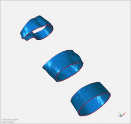
The model I had constructed was essentially that of a conventional plaster cast, although a full conventional shell is vastly overdesigned for its functional requirement of immobilizing the joint. The critical parts are the bands at the two ends - the one encircling the palm at the base of the fingers and the other encircling the forearm - together with the band in the middle that encircles the wrist. (Image below, left) If these three bands remain in rigid alignment, the wrist cannot be flexed in any direction, and the rest of the shell is only there to maintain alignment. Based on this insight, I decided to construct the actual cast from these three bands together with enough stabilizing longitudinal and diagonal strips to maintain rigidity. All of the pieces were cut from the shell via the Trim With Plane command and assembled as a Boolean Union - a simple, functional approach that could be implemented with a few basic commands.
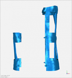
Lastly, I had to separate the model into two pieces that could be assembled about the arm since it could not be constructed in place like a conventional cast. Cutting the model with a plane was easy, and I used a few cylindrical registration pegs with mating sleeves to lock the two halves into the correct position. (Image below, right)
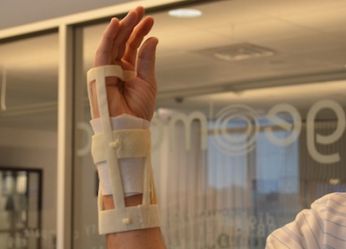
After I printed the components in our 3D printer, I had a lightweight, itch-free, stable arm cast. Better yet, it relieved the pain caused by typing and manipulating the mouse. And, let's be honest, it makes me look cool.
This is only the beginning. We're already seeing a surge of 3D medical device applications. As the necessary tools become more accessible, customized, enhanced medical devices, like casts, will continue to improve medical outcomes. Granted, we can't alleviate all the discomfort of, say, a wrist injury. But at least we can make it easier for future generations when, as adolescents, they crash while showing off by no-hand riding on their brand-new red bicycles.